ADIO-104
Analog and Digital I/O Module for PC/104 Bus


Stock Number:
- 100-7638 / RZ ( Analog Outputs Reset to Zero )
- 100-7638 / RM ( Analog Outputs Reset to Mid-Scale )
Budgetary Pricing:
- $379.00 / 001 - 009
- $363.84 / 010 - 024
- Contact us for More Quantity Discounts
Typical Lead-Time:
- This item is special order. Please contact us for availability and lead-time.

DESCRIPTION
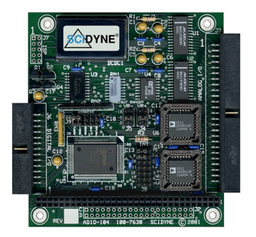
The ADIO-104 is an 8-bit analog and digital input/output module designed to satisfy a broad range of applications. Its generous assortment of functions and capabilities will, in many instances, make the ADIO-104 the only peripheral module required. It conforms to the PC/104 standard and operates on a single +5V power supply.
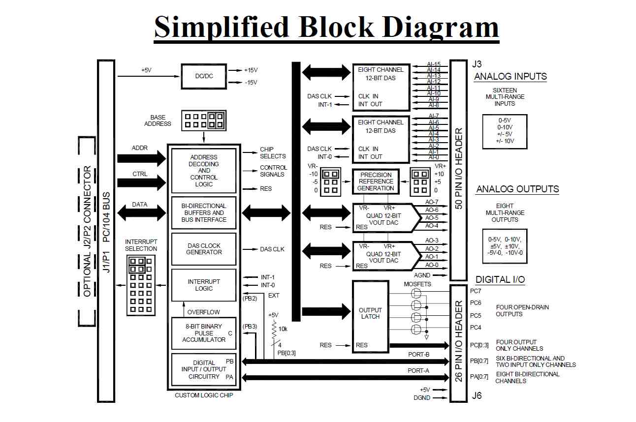
For improved signal integrity analog signals are routed through a 50-Position IDC header featuring alternating grounds signals. All digital I/O connections are routed to a separate 26-Position IDC header.
Analog Inputs
Sixteen 12-bit resolution single-ended analog inputs are provided, each with software programmable input ranges of ±10V, ±5V, +5V, +10V. This capability effectively increases the dynamic range to 14-bits when employing software range-switching techniques. Input protection handles applied voltages up to ±16.5V and continues to function even when power is off. In addition, a fault condition on any input channel will not affect the operation of the remaining channels.
A special feature of the Analog-to-Digital converter is its ability to allow the separate acquisition and conversion times to be individually controlled by the user's software or automatically sequenced by the ADIO-104 hardware.
Analog-to-Digital conversions are initiated by writing a control byte which selects the input channel and sets its range along with other parameters. The ADIO-104 hardware also permits the simultaneous conversion on pairs of similarly configured analog inputs, ideal for phase-coherent data acquisition. The host can determine when a conversion is complete using one of three methods: by simply waiting longer than the conversion time, by polling a status bit, or by having the status bit interrupt the host when it becomes set. A resulting 12-bit value is read as two bytes in an 8+4 format.
Analog Outputs
The eight 12-bit analog outputs share an identical range, which is hardware programmable for several popular values: +5V, +10V, -5, -10, ±5V, and ±10V. An on-board DC/DC converter enables the bipolar and 10V ranges to be achieved while operating from only +5V.
The Digital-to-Analog converters are pre-loaded using an 8+4 bit format. Upon receipt of a single update command, those with new data change, while the remaining channels maintain their previous output voltages glitch-free. This simultaneous update feature is particularly useful in applications which can not tolerate phasing errors between the analog outputs such as servo-motor controls.
All analog output channels feature read-back of the DAC registers. At reset, the outputs are automatically initialized to ZERO or MID scale (RZ and RM models respectively).
Digital I/O
The ADIO-104 features 24 digital I/O channels in the form of three 8-bit ports:
- PORTA is bi-directional and is configured on a nibble (4-bit) basis for input or output operations.
- PORTB has six bi-directional channels and two dedicated input channels. Pull-up resistors are present on the lower nibble which simplifies interfacing to switches and contact closures.
- PORTC has eight dedicated outputs. Four of the channels directly drive on-board 50Vdc open-drain MOSFETs, each with 165ma sink capability. The open-drain outputs can be made TTL/ CMOS compatible with appropriate external pull-up resistors.
During a hardware reset all ADIO-104 bi-directional channels resort to input mode, dedicated output channels are cleared to zero, and open drain outputs go to a high impedance (non-conducting) state.
Pulse Accumulator / Counter
An 8-bit binary Pulse Accumulator is provided for general purpose use. It may be freely written to and read from at anytime. It's input clock is shared with the dedicated input channel PORTB.3. Positive going edges on this channel will increment the count. The counter is cleared to zero during hardware reset.
Roll-Overs (ie; counts 255 ... 0) set an overflow status bit which can optionally interrupt the host. This feature can be used to extend the counting range or interrupt the host after a pre-determined number of input transitions.
External Interrupt
Dedicated digital input PORTB.2 also serves as an external interrupt input. A negative edge transition sets a status bit which can optionally generate a host interrupt.
FEATURES
- Analog I/O and Digital I/O in an economical PC/104 module
- Sixteen 12-bit multi-range analog inputs (±10V,±5V,+5V,+10V)
- Eight 12-bit multi-range analog outputs (±5V,+5V,+10V)
- Two models available, Analog outputs can reset to Zero or Mid-Scale
- 24 digital I/O channels; four 50V open-drain MOSFET outputs
- Pulse Accumulator (counter)
- Single +5 volt power requirement
DOCUMENTATION
- Product Bulletin (pb7638.pdf)
- User's Reference Manual (ADIO-.pdf)
- Example Software (adio_ex1.zip)
- MAX197 - Multi-Range 12-Bit DAS (1042.pdf)
- DAC8412 - D/A converter, Quad, 12-Bit Voltage out (DAC8412_3_d.pdf)
SPECIFICATIONS
| Analog Inputs | |
| General: | Two Data-Acquisition System chips provides sixteen multi-range single-ended analog input channels |
|---|---|
| A/D Resolution: | 12-bit (1 in 4096 of full-scale), 14-bit effective dynamic range using software range-switching techniques |
| Input Ranges: | Each channel has software programmable input range: ±10V, ±5V, +5V or +10V |
| Input current: | Unipolar: 750µA max. Bipolar: 1200µA max. |
| Overvoltage: | ±16.5V protection. A fault condition on any channel will not affect readings on other channels |
| Nonlinearity: | ±1LSB |
| Sampling: | 50,000 samples/sec max. (Host dependent), self-timed or user controlled acquisition. Capable of simultaneous sampling on identically configured pairs; AICH0:AICH8, AICH1:AICH9 and so on. |
| Analog Outputs | |
| General: | Two Quad D/A chips provide eight multi-range analog output channels. Supports simultaneous updates |
| D/A Resolution: | 12-bit (1 in 4096 of full scale) |
| Output Ranges: | Jumper selectable output range: +5V, +10V, -5V, -10V, ±5V or ±10V |
| Reset State: | Depends on model purchased: RZ = DACs value set to zero (0x000) RM = DACs value set to mid scale (0x800) |
| Output Current: | ±5mA max. per output |
| Settling Time: | 10µs max. to within ±0.5LSB of final value |
| Relative Accuracy: | ±1LSB |
| Nonlinearity: | Less than ±1LSB, guaranteed monotonic |
| Digital I/O | |
| General: | 24 digital I/O channels across three 8-bit ports |
| Compatibility: | Unless specified otherwise all channels meet TTL/CMOS signal levels, output current ±5ma |
| PORTA: | Eight bi-directional channels. Configured on a nibble (4-bit) basis for input or output operations |
| PORTB: | PORTB has six bi-directional channels and two input only channels functionally shared with the Pulse Accumulator and External Interrupt. PORTB[0:3] feature 10k pull-up resistors. |
| PORTC: | PORTC is output only. PORTC [4:7] feature 50V/165ma open-drain MOSFETs |
| Miscellaneous | |
| Pulse Accumulator: | Presetable 8-bit binary up counter. Clock input is shared with PORTB.3 and is positive edge sensitive. Overflows are recorded and can optionally generate interrupts. 250khz maximum count rate. |
| External Interrupt: | Input is shared with PORTB.2. Negative edge sensitive. Transitions are recorded and can optionally generate interrupts. |
| Addressing: | 8-bit PC/104 bus. Can be jumpered for any 32 byte block in hosts I/O map, 0x000 through 0x3f0 |
| Interrupt: | Optionally uses one interrupt, jumper selectable IRQ 3,4,5,6,7,9,(10,11,12,14,15)* or Disable. Supports interrupt sharing with other PC/104 modules. Maskable sources: Analog input DAS chips, Pulse Accumulator, and External Interrupt. *Access to these interrupts require optional J2/P2 stack-through connector. |
| Power Requirement: | +5Vdc ±5% @ 385mA typical, user circuitry excluded |
| Dimensions: | PC/104 compliant, 3.55"W x 3.775"L. 8-bit stack-through, optional 16-bit stack-through |
| Environmental: | Operating temperature: 0°C to 65°C (Standard) Non-condensing relative humidity: 5% to 95% CA Residents: Warning - Prop 65 Info |
| Product Origin: | Designed, Engineered, and Assembled in U.S.A. by SCIDYNE Corporation using domestic and foreign components. |
You may also be interested in these products

- Screw-Terminal Boards
- #100-7625
- Easily transition from IDC ribbon cable to field wiring

- Cable Assembly
- #115-7623/5018
- Flat ribbon cable with IDC connector on each end

