XIO-RO8
8 Channel Relay Output Board


DESCRIPTION
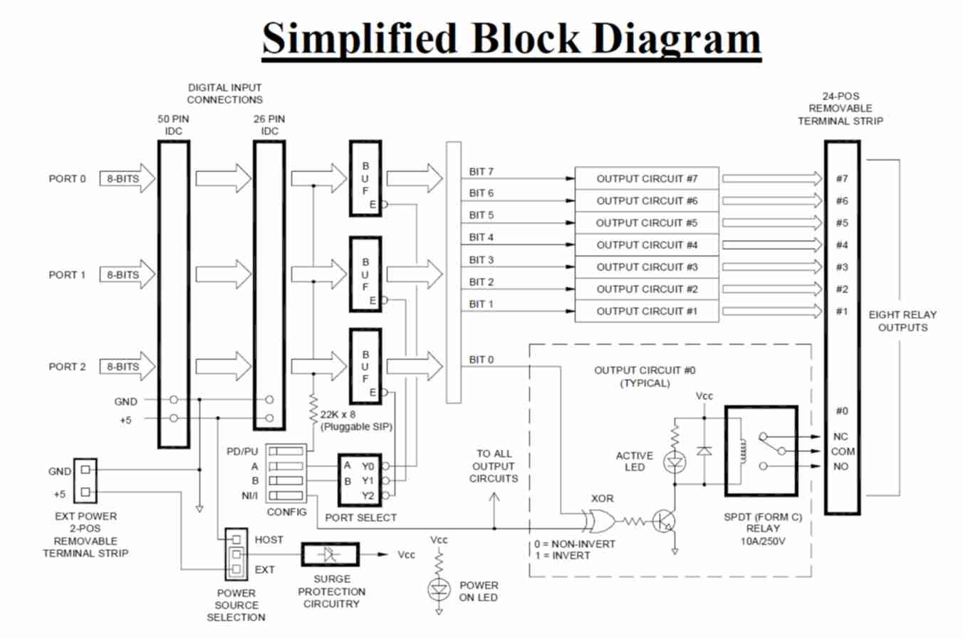
The XIO-RO8 accepts up to three 8-bit TTL/CMOS digital ports and uses one of the ports to control eight isolated 10A SPDT (Form C) relay outputs. Dual IDC input headers directly support the two most common pinout arrangements for digital I/O ports. Other pinouts can be accommodated with simple custom cable assemblies.
A DIP switch configures which one of the three ports will be used, the control signal polarity, and whether the inputs signals will be resistively Pulled-up or Pulled-down. The input resistors serve to keep the XIO-RO8 outputs in a known state in the event the host looses power or becomes disconnected. The remaining two non-selected ports are unaffected and can be used with other circuitry, including additional XIO series boards.
Each bit of the selected port controls a corresponding relay output. Depending on whether the XIO-RO8 is configured for "non-inverted" or "inverted" operation, a relay is activated by its control bit being logic "1" or logic "0" respectively. A status LED for each channel illuminates whenever its relay is energized.
By taking advantage of the buffering circuitry and bussed interconnection nature, a bonus feature can be realized which allows multiple boards to be simultaneously driven in parallel by the same digital port. This effectively creates another output relay "pole" for every XIO-RO8 added. For example, connecting five identically configured XIO-RO8 boards to the same digital port would form the equivalent of eight 5PDT relay outputs.
Independent access to each relay’s Normally-Closed, Normally-Open and Common contacts eases wiring constraints and permits flexible mixing of AC and DC signals. Field wiring is made through a single 24-position removable screw-terminal strip which accepts wires in the range of 12-24AWG.
The XIO-RO8 operates from a single +5Vdc supply which can be provided by the Host through the IDC headers, or externally by means of a two position removable screw-terminal strip.
For ease of installation, the board may be mounted in one of three ways: placed within a 3" SNAPTRACK® (121-0024), by using standoffs, or by attaching it to a DIN rail using SNAPTRACK® and adapter clips (121-0019).
FEATURES
- 8-bit Parallel Interface
- Converts one of three 8-bit digital input ports to eight isolated 10A relay outputs
- Removable Screw-Terminals accept 12-24 AWG field wiring
- 5Vdc only power requirement can be supplied by Host or Externally
- Dual IDC input headers supports the two most common digital I/O pinouts
- Works with products from SCIDYNE and as well as from other manufactures
- Mounts using 3" SNAPTRACK®, Standoffs or on DIN rail
DOCUMENTATION
- Product Bulletin (pb7632.pdf)
- User's Reference Manual (XIO-RO8.pdf)
SPECIFICATIONS
| General: | |
| Description: | Eight channel high current relay output board |
|---|---|
| Power requirement: | +5Vdc ±5% @ 700mA typical, all relays activated. Host or Externally supplied, "Power-On" LED |
| Environmental: | Operating temperature: -20°C to 70°C Non-condensing relative humidity: 5% to 95% CA Residents: Warning - Prop 65 Info |
| Dimensions: | 3.00" W x 10.00" L x 1.35" H |
| Mounting: | Mount using Standoffs, SNAPTRACK® or DIN Rail |
| Isolation: | Board-to-output: 500V, DC or AC Isolation between adjacent relay outputs channels: 250V maximum |
| Product Origin: | Designed, Engineered, and Assembled in U.S.A. by SCIDYNE Corporation using domestic and foreign components |
| Digital Inputs: | |
| General: | 24 digital inputs arranged as three individual 8-bit ports. User configures which 8-bit parallel port will be used. Connects using 50-Pin and 26-Pin IDC headers with mechanical latches |
| Input level: | TTL/CMOS compatible Logic "0": 1.35Vdc maximum Logic "1": 3.15Vdc minimum |
| Control polarity: | Switch selectable for Non-Inverted or Inverted operation |
| Input impedance: | Selected port: 22kΩ typical, switch selectable as Pull-Up or Pull-Down. Non-Selected Port: 1MΩ typical |
| Relay Outputs: | |
| General: | Eight SPDT (Form C) sealed electro-mechanical relays, Break-Before-Make operation, "Active" LED for each channel |
| Power handling: | DC: 8 Ampere @ 30Vdc maximum (resistive load) AC: 10 Ampere @ 125VRMS maximum (resistive load) |
| Switching capacity: | 100ma, 5Vdc minimum, 1200 VA, 240W maximum, 250Vac, 125Vdc |
| Contact resistance: | 100mΩ maximum, AgSnO2 contacts |
| Operate time: | 10ms maximum (activate or release) |
| Bounce time: | Operate: 0.6ms Release: 7.2ms |
| Switching frequency: | 1,800 operations per hour under rated load |
| Service life: | 10,000,000 operations minimum |
You may also be interested in these products

- Cable Assembly
- #115-7623/5018
- Flat ribbon cable with IDC connector on each end

- Screw-Terminal Boards
- #100-7625
- Easily transition from IDC ribbon cable to field wiring

- SNAPTRACK
- This non-conductive, rigid extruded PVC channel allows for fast and secure "Snap-In" mounting of assemblies and circuit boards.

