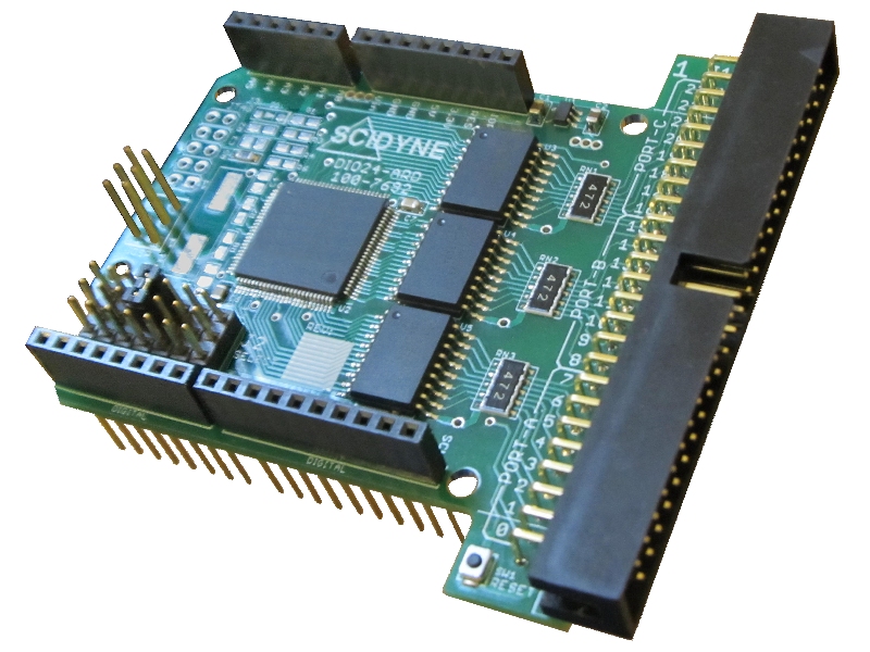
DIO24-ARD
24-Channel Digital I/O Interface for Arduino, Genuino, and Compatibles


DESCRIPTION
The DIO24 ARD adds 24 digital I/O channels to an Arduino/Genuino UNO, MEGA 2560, or other (+5 Volt) compatibles. The specialized circuitry makes it easy to connect Solid-State I/O Racks, Switches, Relays, LEDs, and many other commonly encountered peripheral devices.
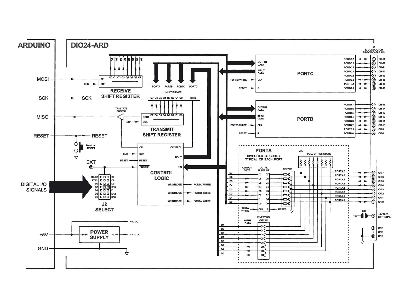
External devices connect to the DIO24-ARD through a single 50 conductor IDC ribbon cable style connector. The pin-out is fully compatible with standard 8, 16 and 24 position Solid State I/O module racks available from a variety of third-party vendors.
Each DIO24-ARD channel is individually defined through software to operate as either an input or output. Channels configured as outputs are capable of sinking 85ma.
The DIO24-ARD appears as a Serial-Peripheral-Interface (SPI) device. Only one Arduino digital output is required to function as the dedicated board Enable leaving all remaining Arduino digital I/O available for other purposes.
Get things up and running quickly with the supplied library. It includes routines for bit manipulation, port read and write, and controlling data direction.
FEATURES
- 24 Individually programmable digital I/O channels
- High output current capability (85ma sink)
- Use supplied library or standard Arduino SPI functions
- Jumper selectable Enable signal selection
- Stack-Through connectors accommodate multiple shields
- Drives industry standard Solid State I/O Module Racks and other peripheral devices
DOCUMENTATION
- User's Reference Manual (dio24-ard_manual.pdf)
- NEW Arduino Library (SCIDYNE_DIO24ARD.zip)
- Non-Library Example Software (dio24-ard_examples.zip)
- Independent Video Review YouTube
SPECIFICATIONS
| Number of Channels: | 24 Individually programmable digital I/O channels, non-isolated |
|---|---|
| Input Level: | Logic 0 = 0.8vdc maximum, -0.3vdc minimum Logic 1 = 2.0vdc minimum, 5.6vdc maximum |
| Output Level: | Logic 0 = < 1.0vdc (15ma load) Logic 1 = > 2.5vdc (500ua load) |
| Output Current, Per Channel (Max.): | Source: 1.0ma, passively by 4.7k Pull-Up resistor to +5V Sink: 85ma, actively by open-collector transistor to 0V (GND) |
| Software: | Uses standard Arduino SPI (ICSP) library functions |
| Communications: | Serial-Peripheral-Interface (SPI) through Arduino ICSP connector. Requires one user designated Arduino digital output for enable, jumper selectable. EXT input for optional external enable signal. SPI Configuration: Mode: 0 SCK: 8 MHz maximum |
| Field Connections: | 50 Position IDC Ribbon Cable |
| Arduino Connections: | Stack-through connectors allows multiple shields Power: 8 Pos. x 1 Row Analog: 6 Pos x 1 Row Digital: 8 Pos x 1 Row, 10 Pos. x 1 Row ICSP: 3 Pos x 2 Row |
| Power Requirement: | Supplied by Arduino, +5vdc +/-5% @ 45ma typical, all ports written as 0xff, external loads excluded. |
| Dimensions: | 2.80"W x 2.97"L x 1.04"H overall, Modified Arduino R3 format |
| Environmental: | Operating Temperature: -40°C to +70°C Non-Condensing Relative Humidity: 5% to 95% |
| Compliance: | RoHS CA Residents: Warning - Prop 65 Info |
| Product Origin: | Designed, Engineered, and Assembled in U.S.A. by SCIDYNE Corporation using domestic and foreign components. |
You may also be interested in these products

- Cable Assembly
- #115-7623
- Flat ribbon cable with IDC connector on each end

- Screw-Terminal Boards
- #100-7625
- Easily transition from IDC ribbon cable to field wiring


