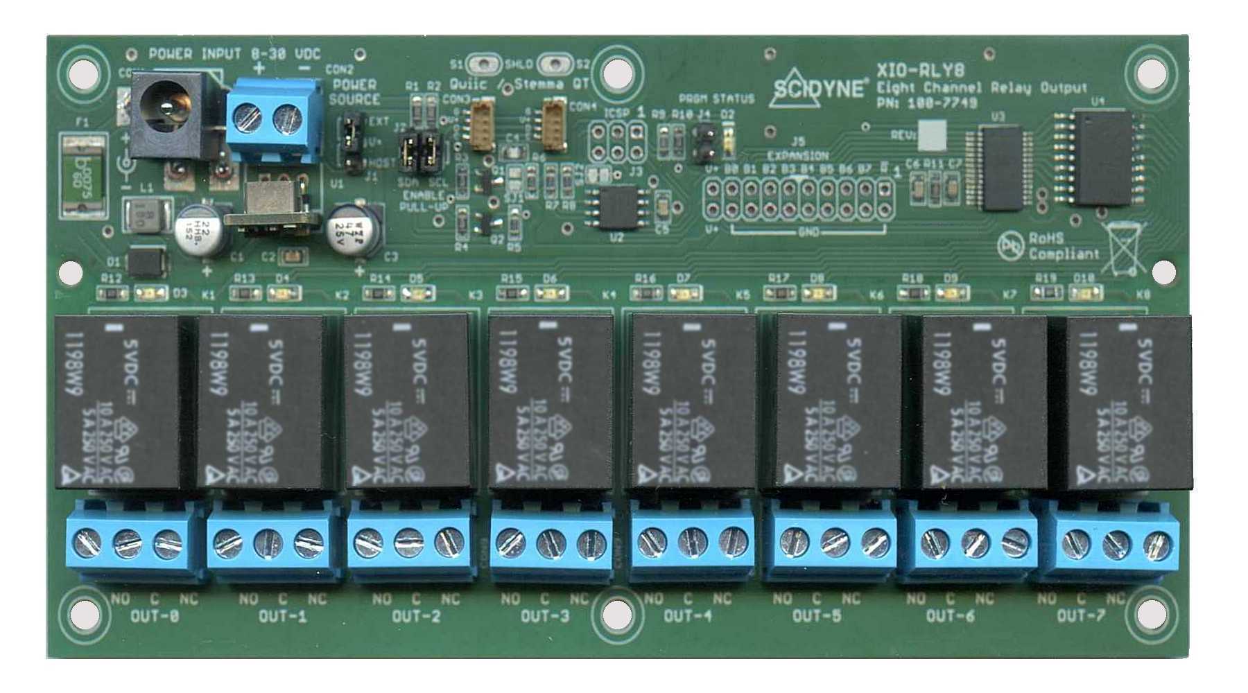
XIO-RLY8
8 Channel Relay Output Board with Qwiic/Stemma QT I2C Interface for Raspberry Pi, ESP32, Arduino, Microcontrollers, and more
Stock Number:
- 100-7749
Limited Time Introductory Price
- $39.95 each
Typical Lead-Time:
- Stock - 2wks

DESCRIPTION
Powerful 8-Channel Relay Control for Embedded Systems
The XIO-RLY8 is an 8-channel relay output board that adds industrial-grade switching capability to any device with I2C communications including Raspberry Pi, ESP32, Arduino, Microcontrollers, and FPGAs.
Designed for industrial automation, production test equipment, building controls, and custom machine control applications, the XIO-RLY8 enables low-power controllers to operate high-power equipment, including motors, pumps, solenoids, lighting systems, alarms, and HVAC equipment. Featuring eight isolated 10A SPDT relays, configurable I2C addressing, and flexible power options, the XIO-RLY8 provides a simple, reliable way to control high-power AC and DC loads from low-voltage embedded systems.
Dual Qwiic/Stemma QT connectors allow fast and easy system setup. In addition, the I2C circuitry has been engineered to operate at either 3.3V or 5V and is rated up to 400 kHz making the XIO-RLY8 highly compatible.
Versatile mounting options include DIN rail clips, track mount, and standoffs. By locating the relays near field wiring and away from the controller, the XIO-RLY8 improves system noise immunity and helps protect sensitive control electronics from electrically noisy field signals.
FEATURES
- Eight isolated 10A SPDT (Form C) relay outputs
- Compatible with Raspberry Pi, ESP32, Arduino, and other I2C-enabled devices
- Dual Qwiic/Stemma QT connectors for easy daisy-chain expansion
- Occupies a single I2C bus address, user configurable between 0x08 - 0x77
- Supports both 3.3V and 5V I2C logic levels and speeds up to 400 kHz
- Operates from 5V bus power or an external 8-30VDC supply
- Built-In functions ease software development
- LEDs provide instant visual indication of relay and board activity
- Field wiring Screw-Terminals accept 12-24 AWG wires
- Mounts using DIN rail clips, Standoffs, or Track Mount
DOCUMENTATION
- User's Reference Manual (XIO-RLY8.pdf)
- Arduino library and examples (SCIDYNE_XIORLY8.zip)
- Raspberry Pi Python and C/C++ examples (SCIDYNE_RPi_XIO-RLY8.zip)
SPECIFICATIONS
| General: | |
| Description: | Eight channel Relay Output Board with Qwiic/Stemma QT I2C interface |
|---|---|
| Power requirement: | Jumper determines source, “Power-On / STATUS” LED EXT: 8-30 VDC @ 4W typical. Screw terminal or 2.1mm x 5.5 mm barrel jack HOST: +5Vdc ±5% @ 800mA typical, supplied by Qwiic/Stemma QT connection |
| Mechanical: | |
| Dimensions: | 3.00" W x 6.00" L x 0.825" H |
| Weight: | 8oz |
| Mounting: | Mounts using DIN Rail, Standoffs, or Track Mount |
| Communications: | |
| Connections: | Two Qwiic/Stemma QT connections, 4-Wire female 1.0mm JST style |
| Addressing: | Requires one unique 7-bit I2C address, Factory default address is 0x30 User programmable between 0x00 – 0x7F, some addresses are reserved and should be avoided |
| Pull-Ups: | Jumper enabled 2.0K Pull-Ups on SDA and SCL signals referenced to HOST V+ |
| Bus Voltage: | Level-Translator circuitry support 3.3V or 5.0 V signal levels |
| Protocol / Software: | Use standard I2C functions. Supplied with software examples for Arduino and Raspberry Pi |
| Speed: | Standard (100 kHz), Fast (400 kHz) |
| Latency: | 5ms maximum, command received to excecution / completion |
| Relay Outputs: | |
| General: | Eight SPDT (Form C) sealed electro-mechanical relays, Break-Before-Make operation, “Active” LED for each channel |
| Connections: | Three position Screw-Terminal for each channel. Accepts up to 12AWG wire |
| Power handling: | DC: 8 Ampere @ 30Vdc maximum (resistive load) AC: 10 Ampere @ 125VRMS maximum (resistive load) |
| Switching capacity: | 100ma, 5Vdc minimum, 1200 VA, 240W maximum, 250Vac, 125Vdc |
| Contact resistance: | 100mΩ maximum, AgSnO2 contacts |
| Operate time: | 10ms maximum (activate or release) |
| Bounce time: | Activate: 0.6ms Release: 7.7ms |
| Switching frequency: | 1,800 operations per hour under rated load |
| Service life: | 10,000,000 operations per relay minimum |
| Isolation: | Board to Output: 250V DC or AC Between adjacent outputs channels: 250V maximum |
| Environmental: | |
| Operating temperature: | -20°C to 70°C |
| Compliance: | RoHS / Lead-Free, Conflict-Mineral Free (view policy), CA Residents: Warning - Prop 65 Info |
| Product origin: | Designed, Engineered, and Assembled in U.S.A. by SCIDYNE® Corporation using domestic and foreign components |
You may also be interested in these products
- Cable Assembly
- #115-7623/5018
- Flat ribbon cable with IDC connector on each end
- Screw-Terminal Boards
- #100-7625
- Easily transition from IDC ribbon cable to field wiring

- DIN Rail Clips
- DIN Rail Mounting Clips