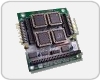
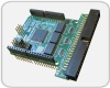
DIO24-104
24-Channel Digital I/O Module for PC/104 Bus
Stock Number:
- 100-7543
Budgetary Pricing:
- $98.00 / 001 - 009
- $94.08 / 010 - 024
- $90.32 / 025 - 049
- $86.78 / 050 - 099
- Contact us for More Quantity Discounts
Typical Lead-Time:
- Stock - 2wks

DESCRIPTION
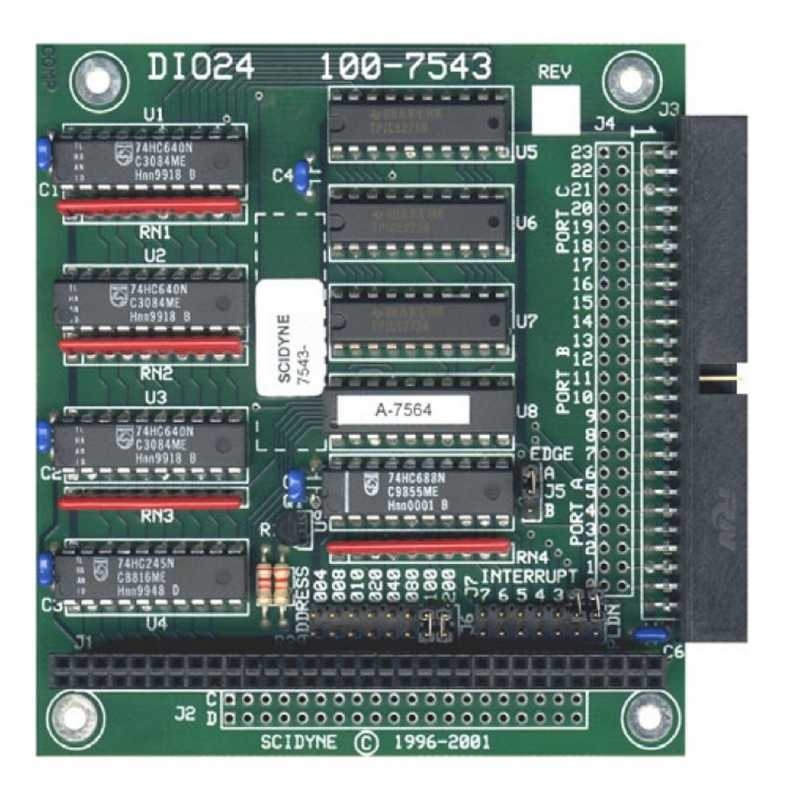
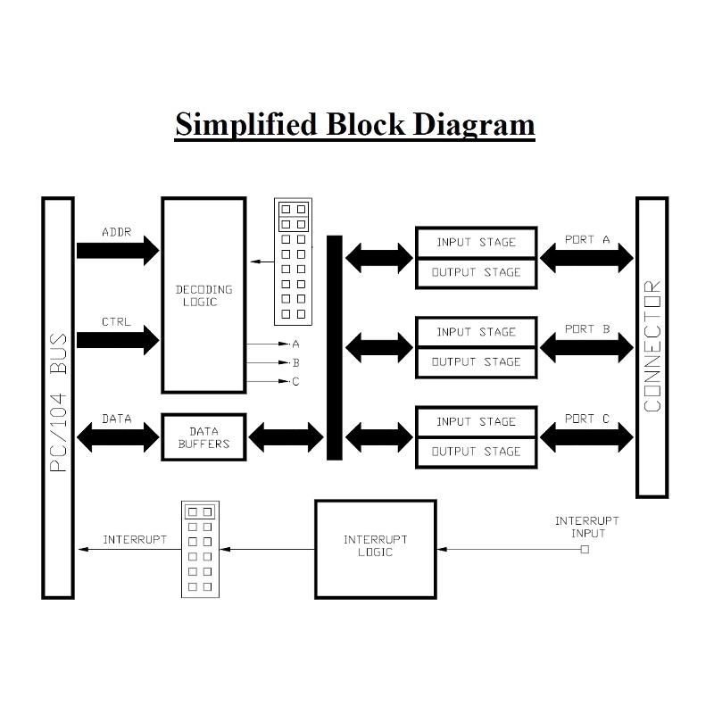
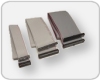
The DIO24-104 is a 24-channel digital input/output module designed for PC/104 bus computers. It is fully compatible with industry standard 8, 16 and 24 position Solid State I/O racks allowing practically any combination of AC, DC, Input, or Output digital signals to be monitored and controlled. The DIO24-104 can also be used to attach switches, relays, LEDs, solenoids, terminal boards, and a variety of other commonly encountered peripheral devices to a PC/104 bus computer
Specially designed I/O circuitry permits each channel to be individually defined through software as being an input or output. Channels configured as outputs are capable of sinking 85ma of current. In addition, any single input channel can be configured to interrupt the host when that channel changes state. The polarity can be set to interrupt on either level-edge and the transition is latched so that even short duration pulses are captured. A 50-conductor IDC ribbon cable is used to make off-board connections.
FEATURES
- 24 Individually programmable digital I/O channels
- High output current capability (85ma sink per channel)
- Input interrupt capability
- Output Read-Back status eases software development
- Directly connects to standard Solid State Relays Racks and peripheral devices
- CMOS construction assures low power consumption and greater noise immunity from external electrical sources
DOCUMENTATION
- Product Bulletin (pb7543.pdf)
- User's Reference Manual (DIO24.pdf)
SPECIFICATIONS
| Number of Channels: | 24 Individually programmable digital Input/Output channels, non-isolated |
|---|---|
| Input Level: | Logic 0 = 0.8vdc maximum, -0.6vdc minimum Logic 1 = 2.0vdc minimum, 5.6vdc maximum |
| Output Level: | Logic 0 = < 0.4vdc (15ma load) Logic 1 = > 2.0vdc (1ma load) |
| Output Current, Per Channel (Max.): | Source: 2.5ma, Sink: 85ma |
| Addressing: | Requires 4 consecutive I/O bytes, base address jumper selectable between 0 and 1020 decimal (0 to 0x3fc hexadecimal) |
| Interrupts: | Any single input channel can be configured to interrupt the host computer when that channel changes state. Jumper selectable for IRQ 3, 4, 5, 6, 7, or 9 ( Note: IRQ9 is re-directed as IRQ2 on most AT computers). Selectable positive or negative polarity, level-edge Pulse detection 2μs pulse width minimum. |
| Interrupt Sharing: | Fully supported including a read-only interrupt status register |
| Power Requirement: | +5vdc ±5% @ 20ma typical, external loads excluded |
| Connections: | J1/P1: 8-Bit stack-through PC/104 Bus, 64 Position J2/P2: 16-Bit PC/104 Bus, 40 Position (optional 16-bit stack-through) J3: I/O Connector, 50 Position Keyed IDC Ribbon Cable, compatible with standard 8, 16 and 24 position Solid State I/O module racks |
| Dimensions: | PC/104 compliant, 3.6"W x 3.8"L x 0.6"H. 8-Bit stack-through. Holes provided for adding optional J2/P2 connector creating 16-bit stack-through compatibility |
| Environmental: | Operating Temperature: -40°C to 85°C Non-Condensing Relative Humidity: 5% to 95% CA Residents: Warning - Prop 65 Info |
| Product Origin: | Designed, Engineered, and Assembled in U.S.A. by SCIDYNE Corporation using domestic and foreign components. |
You may also be interested in these products
- Cable Assembly
- #115-7623/4018
- Flat ribbon cable with IDC connector on each end
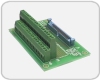
- Screw-Terminal Boards
- #100-7625
- Easily transition from IDC ribbon cable to field wiring